BRIEF
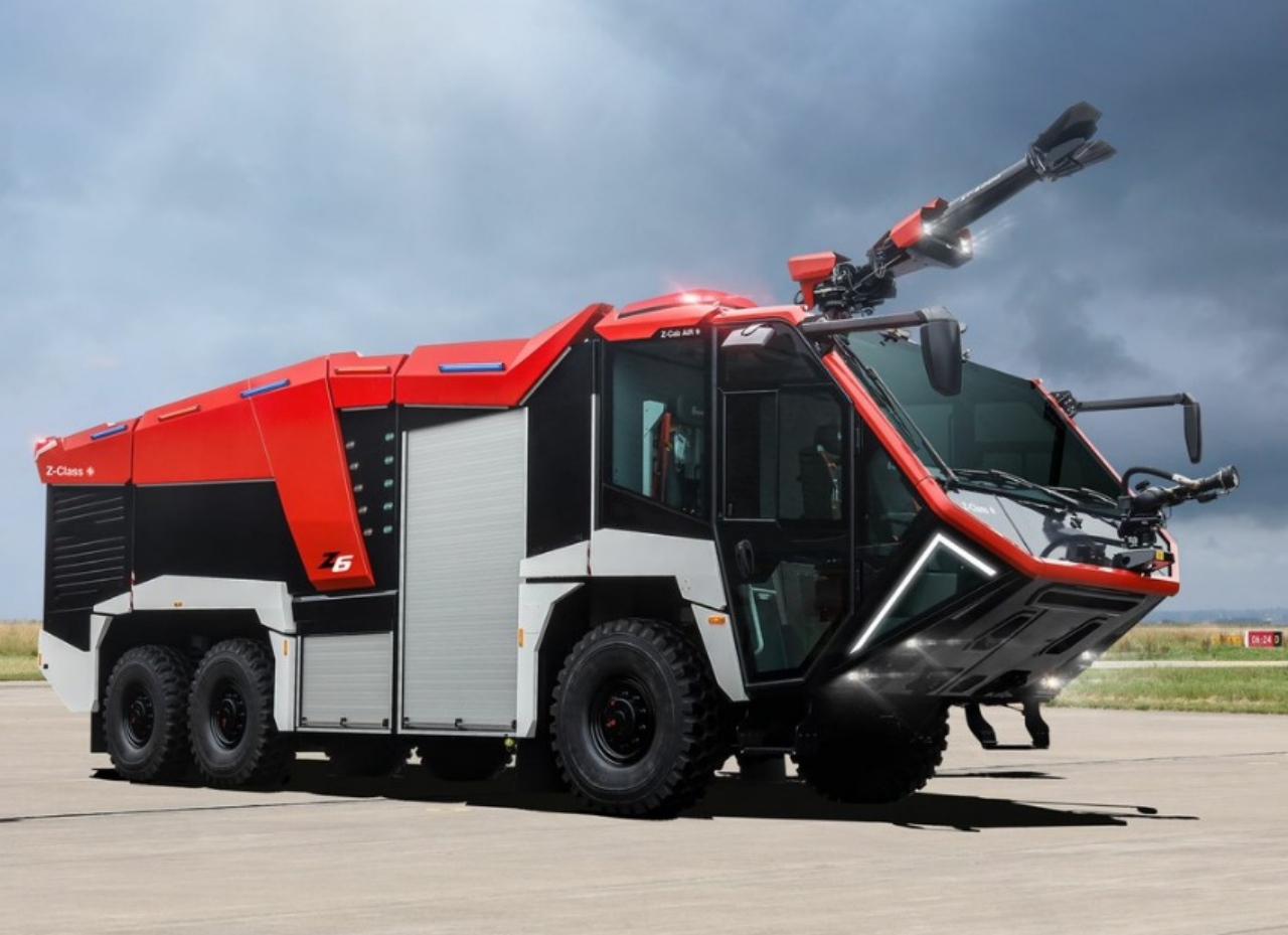
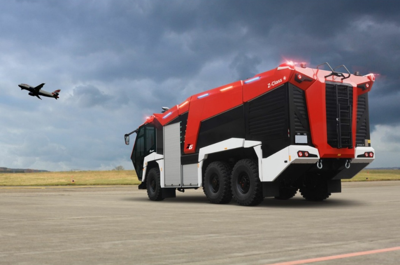
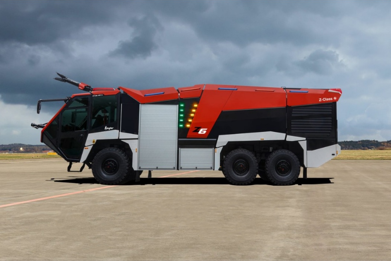
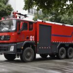
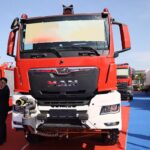
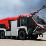
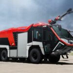
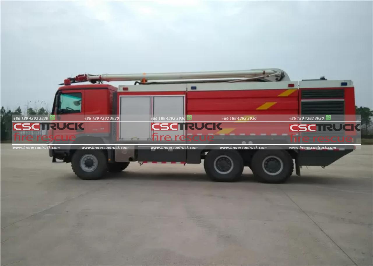
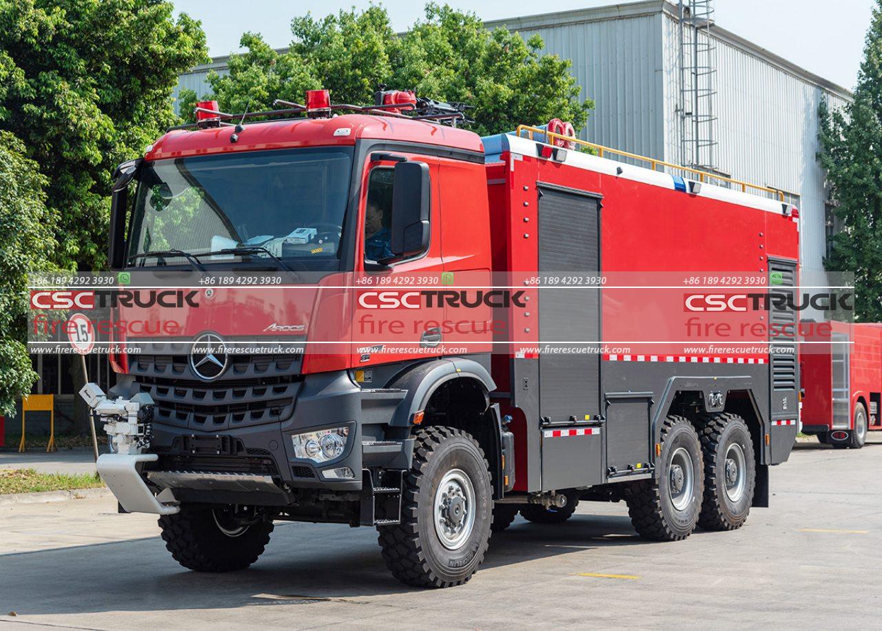
The CSCTRUCK Fire Rescue Truck 6×6 770HP 16000 liters ARFF fire engine is a powerhouse of innovation, combining robust engineering, immense firefighting capacity, and cutting-edge technology. Designed for demanding emergency scenarios, this advanced vehicle is built on the TITAN T39-770 chassis with a 6×6 drivetrain, providing exceptional off-road performance. Its ability to climb gradients of up to 50% ensures reliable access to even the most challenging and remote terrains.
At its core is the SCANIA DC16 386 V8-cylinder diesel engine, a marvel of engineering delivering a staggering 770 horsepower at 1,800 rpm. This water-cooled engine is EURO V compliant, balancing immense power with environmental responsibility. With a maximum permissible weight of 39,000 kg, the fire engine not only supports heavy-duty components but also maintains a top speed exceeding 120 km/h, making it swift and efficient for critical operations.
The fire truck’s firefighting capabilities are where it truly excels. It features a 13,500-liter water tank made of durable composite material, complemented by a 1,700-liter foam tank and a 250 kg dry powder unit. These components enable versatile firefighting strategies tailored to various emergency scenarios. The vehicle is equipped with a PN 10-8000-1M centrifugal fire pump, which can deliver an impressive 8,000 liters per minute at 10 bar. The pump is paired with an 8,000 l/min foam admixing system, ensuring efficient deployment of foam for large-scale fires.
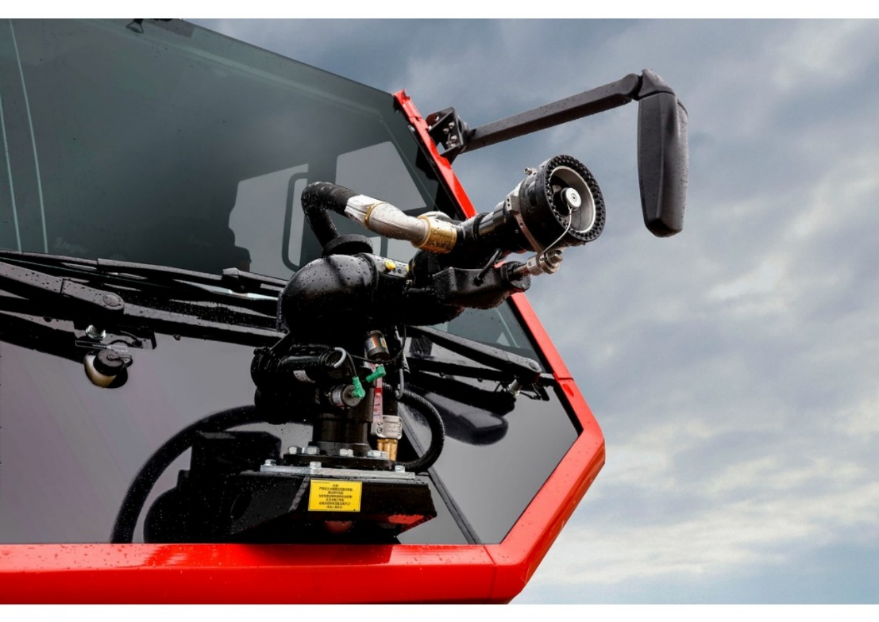
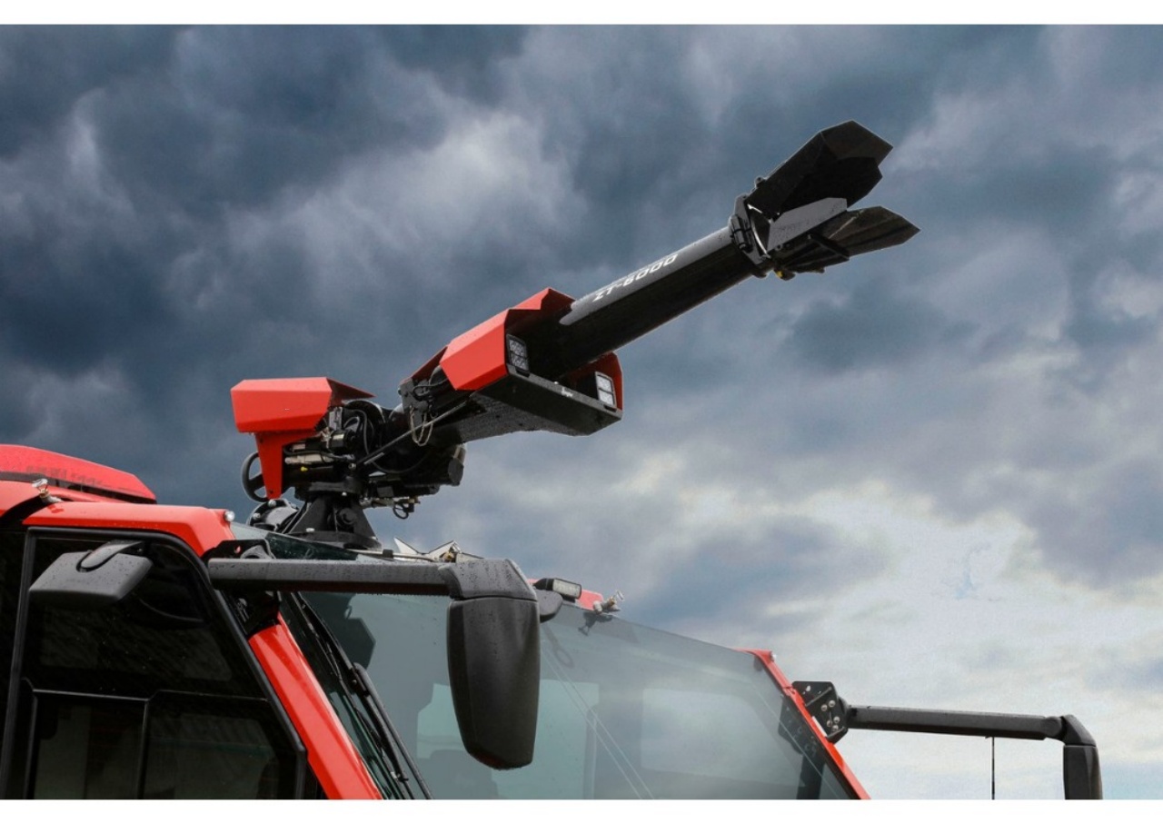
For precision in firefighting, the truck includes advanced turret systems. The Ziegler roof turret ZT-6000 has a discharge capacity of 6,000 liters per minute of water or 3,000 liters per minute of foam, operating at 10 bar pressure. This turret is ideal for tackling high-intensity fires from a distance. The truck is further equipped with a Ziegler bumper turret, which offers a discharge rate of approximately 1,800 liters per minute at 8 bar, providing additional flexibility and rapid response capabilities.
The CSCTRUCK Fire Rescue Truck’s design emphasizes operational efficiency and quick response. Its sturdy construction, paired with advanced technology, ensures reliability and effectiveness in various environments, from urban settings to rugged terrains. The combination of its massive water and foam capacities, state-of-the-art pump systems, and precision turrets makes it a vital asset for combating fires, safeguarding property, and protecting lives.
This ARFF (Aircraft Rescue and Firefighting) fire engine is a testament to modern engineering excellence. It seamlessly integrates performance, reliability, and advanced firefighting technology, making it indispensable for tackling emergencies in airports, industrial complexes, and other high-risk environments. With its blend of power, agility, and efficiency, the CSCTRUCK Fire Rescue Truck sets a high standard in the realm of firefighting equipment, ensuring readiness for the most demanding rescue operations.
FEATURES
- Powerful Engine and Performance:
Built on the TITAN T39-770 chassis with a 6×6 drivetrain, the vehicle boasts a SCANIA DC16 386 V8-cylinder diesel engine producing 770 horsepower, enabling it to handle gradients up to 50% and reach speeds exceeding 120 km/h. - Exceptional Firefighting Capacity:
Equipped with a 13,500-liter water tank, a 1,700-liter foam tank, and a 250 kg dry powder unit, the truck supports versatile firefighting strategies for various emergencies. - High-Performance Pump and Foam System:
The PN 10-8000-1M centrifugal fire pump delivers 8,000 liters per minute at 10 bar, paired with an 8,000 l/min foam admixing system for efficient large-scale firefighting. - Advanced Turret Systems:
The Ziegler roof turret ZT-6000 delivers up to 6,000 liters per minute of water or 3,000 liters per minute of foam, while the Ziegler bumper turret adds flexibility with a discharge rate of 1,800 liters per minute. - Rugged and Versatile Design:
Built for demanding environments, this fire truck combines sturdy construction and cutting-edge technology, ensuring reliable performance in urban, industrial, and remote terrains, particularly in airport and high-risk settings.
SPECIFICATION
| 000 | Major Components: | ||
| 090 | TITAN chassis T39-770 / 6×6 / STAGE V | ||
| 110 | ZIEGLER water tank 13.500 L / Foam tank 1.700 L | ||
| 115 | Powder extinguishing unit 250 kg | ||
| 200 | ZIEGLER Z-Cab Air 1+3 | ||
| 300 | ZIEGLER ALPAS Superstructure | ||
| 400 | ZIEGLER FPN 10-8000-1M | ||
| 410 | ZIEGLER foam admixing system EAD | ||
| 430 | ZIEGLER quick intervention unit | ||
| 440 | ZEIGLER roof turret | ||
| 440 | ZIEGLER bumper turret | ||
| Design logo/labeling according to customers’ samples and instructions. | ||||
| Controls: These are marked using labeling in the English language or clear pictures. | ||||
| Maker’s nameplate: | At the driver’s door the maker’s nameplate, 105 mm x 74 mm, acc. to DIN 825, is provided. | |||
| Diagram: Schematic pipework diagram on/at pump bay panel | ||||
| Chassis: | Chassis: rims: | black black | RAL 9005 RAL 9005 |
|
| Superstructure: | driver’s cab: Superstructure | red red | RAL 3000 RAL 3000 |
|
| Roller shutters: Aluminium natural colored equipment lockers inside: Aluminum natural colored mudguards: White RAL 9010 front and rear bumpers: black RAL 9005. | ||||
| Undercoating: The lower side of the equipment locker superstructure is painted with durable undercoating Corrosion protection: Corrosion protection for long-term use of the chassis and the firefighting superstructure. |
||||
| 90 Chassis: Type: TITAN / T 39-770 / 6×6 / STAGE V |
||||
| Three-axle chassis, all-terrain capability, permanent all-wheel drive | ||||
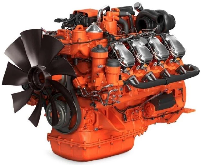
| Engine : SCANIA DC16 386, V8-cyl. Diesel engine, water-cooled, (rearward) Direct injection, turbocharged with diagnostic plug for connection with the SCANIA diagnostic system. | ||||
 |
||||
| Piston displacement. 16.400 ccm Max. Output: 566 KW ( 770 HP ) at 1.800 rpm (According to SCANIA Cat.) Max. Torque: 3.183 Nm at 1.500 rpm (According to SCANIA Cat.) |
||||
| Load-proof for firefighting use (-25°C up to +50° C) | ||||
| Engine brake via throttle valve in exhaust line | ||||
| CAN-BUS interface for body manufacturer via J1939 protocol. | ||||
| Electric cooling water pre-heating system 230V / 1,5kW (via external power supply) for constant engine preheating. |
||||
| Fuel-filter heating (with water separator) for driving engine | ||||
| Total service reliability of the engine at minimum permissible oil level, up to 50 % longitudinal inclination respect. Up to 30° lateral inclination provided (both inclinations are possible at the same time). | ||||
| The chassis is designed for an ambient temperature range of -25°C up to +50°C. | ||||
| Compressor: Compressed-air generator in reinforced design driven from the vehicle engine, vehicle ready to drive in less than one minute from start (up from 0 bar/psi). | ||||
| Air conditioning compressor: Air conditioning compressor driven from the vehicle engine |
||||
| Air filter: Dry air filter with exchangeable cartridge and dirt indication | ||||
| Cooling: Water cooling unit, thermostatically controlled, mounted rear side Electric filling level control of the expansion tank Maximum load-proof for firefighting use (-25°C up to +50 °C) for a minimum of 2 hours of permanent firefighting pump operation. The cooling system is protected against soiling under extreme conditions. (Pusher type cooling fan) |
||||
| Exhaust: Rear side, with one stainless steel exhaust silencer | ||||
| The exhaust collection pipe vertically led up over the superstructure with a rain flap on the tail pipe. | ||||
| Exhaust treatment with SCR System Ad Blue Injection with supply and dosage unit |
||||
| EU STAGE V emission standard |
| Gearbox: Kessler LV3000-PTO Continuously Variable Transmission comprising three driving ranges with integrated Power Shift PTO 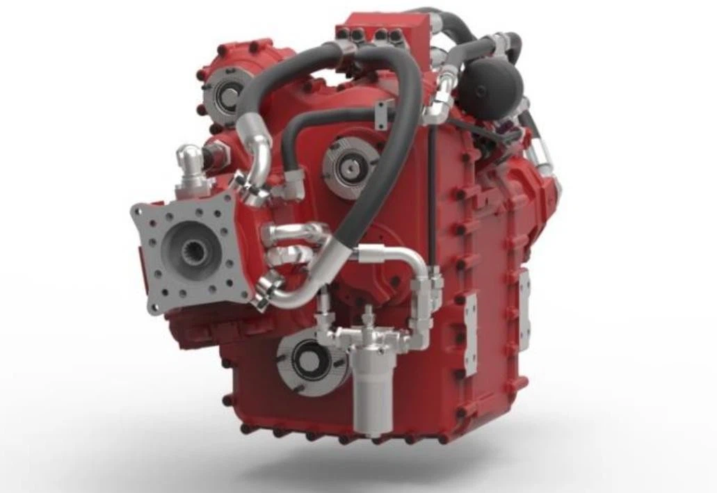 |
||||
| Transmission details Input torque: up to 3500 Nm Output torque: up to 17000 Nm Input speed: 600 to 1800 rpm Ratios: stepless |
||||
| Permanent all-wheel drive with differential lock Power distribution: 33% front axle – 67% rear axles |
||||
| PTO connection SAE D for emergency steering pump | ||||
| The continuously variable transmission allows any driving speed independent from the turning speed of the Diesel engine. The stepless ratio of the transmission results in high drive comfort. |
||||
| Power Shift PTO for centrifugal fire pump PTO torque: up to 1500 Nm PTO speed: up to 2700 U/min Ratio: 1,5 Flange type: cross serrated T150 |
||||
| Turning direction: opposite than Diesel engine Pump and roll speed: full driving range | ||||
| The Power Shift PTO can be actuated at any driving speed. | ||||
| The chassis can be towed without disconnecting the driveshafts up to a distance of 10 km (with limited speed) | ||||
| Axles: KESSLER Planetary hub axles | ||||
| 1. Front axle: Steerable with differential lock
|
||||
| 1. Rear axle: With longitudinal and lateral diff. lock
|
||||
| 2. Rear axle: With differential lock
|
||||
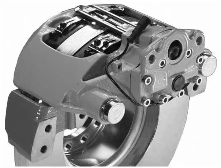
| All axles with compressed-air disk brakes
|
||||
| Differential lock: Longitudinal and lateral locks electrically switchable in the driver’s cab |
||||
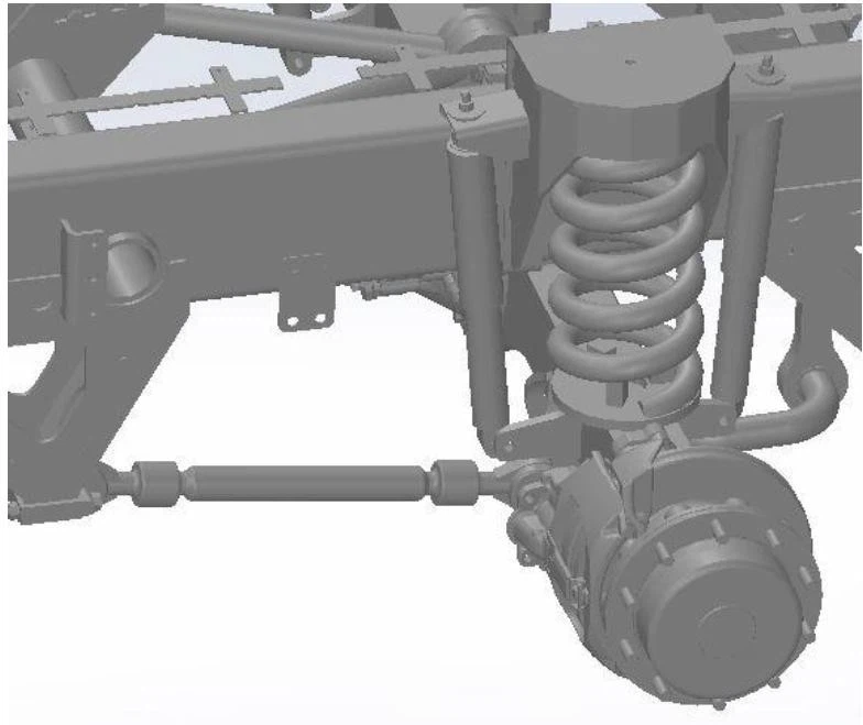
| Suspension: Progressive Coil spring suspension with double-bumpers and stabilizers to guarantee superior off-road capabilities
|
| Tires: | Single tire, tubeless | ||
| Single-tyre front axle | Michelin 16.00 R 20 XZL | ||
| Single-tire rear axles | Michelin 16.00 R 20 XZL | ||
| 1x K-920-000128 1x Spare wheel, supplied loose | |||
| Brake unit: Dual circuit brake system with ABS (anti-lock system) and EBS (electronic brake system), complied with the requirements of ECE R13 (6 channel anti-lock system, FA, RA-1, RA-2) | |||
| Compressed-air disk brakes are effective on the front axle and rear axles. | |||
| Spring-loaded parking brake effective on rear axles | |||
| Service brake performance: 32 km/h – 0 within 10 m 64 km/h – 0 within 40 m Holding capacity min. 50% slope |
|||
| Parking brake and Emergency Brake performance: 64 km/h – 0 in less than 88 m Holding capacity up to 30% slope |
|||
| Compressed-air dryer, electrically heated | |||
| Tire inflation tool-kit | |||
| Air tanks in aluminum with automatic operated drain valves | |||
| 1x K-920-000101 Emergency release for parking brake, activated from inside cabin | |||
| Steering: Ball-and-nut type power steering gear (Bosch) Dual circuit with emergency steering pump (effective on front axle) |
|||
| Driving position: Central left-hand drive The steering wheel adjustable in height and inclination |
|||
| Frame: Torsional stiffness ladder frame with box profile Longitudinal beams with crossbars and solid end bar rear side. |
|||
| Electrical system: Voltage 24 V, IP65 Lead-Batteries: 2 x 12 V / 180 Ah (maintenance free) |
|||
| Alternator: 1 x 150 A Manually operated switch directly located at the battery |
|||
| Dashboard: In the digital TFT display all driving information and indicators for the chassis are provided effectively and can be seen by the driver. | |||
| Interface for an Alarm-Start-Unit: Via this alarm start interface, three automatic start repeats for the driving engine to be triggered. |
|||
| Interfaces at modular extension: Unmistakable electric plug-type connections at the individual components. |
|||
| Connections with the electric and electronic modules via coded plug-type connectors (confusion- and shake-proof). | |||
| Exact interface definition chassis/superstructure in compliance with the mounting guidelines of the chassis manufacturer. | |||
| Vehicle dimensions: Total length approx.11.800 mm Total width (without mirror) 3.000 mm Total height approx. 3.700 mm Wheel base 4.750 / 1.600 mm The angle of approach is 30 degrees The angle of departure is 30 degrees Max. climbing ability 50 % The statical tilt angle is 30 degrees The diameter of the turning circle is approx. 31 m Ground clearance below the axles approx. 350 mm |
|||
| Vehicle weights: GVW permissible 39.000 kg Front axle permissible 13.000 kg ( 1 x 13.000 kg) Rear axle permissible 26.000 kg ( 2 x 13.000 kg) |
|||
| Fuel tank: 300 Liter (in Aluminum) with lockable cab, chain strainer, and drain at bottom 38 Liter Ad-Blue |
|||
| Performance: Max. speed >120 km/h Acceleration from 0 – 80 km/h less than approx. 28 sec |
|||
| 100 Built on executions of chassis by the bodybuilder: 1x K-920-000152 2x shackles in front |
|||
| 1x K-920-000155 2x shackles in rear | |||
| 110 Water / Foam tank: 1x K-930-000003 The water tank is made of corrosion-resistant PP composite material The PP water tank has a capacity of up to 13.500 l usable amount of water. The tank surface can be walked on and is provided with an anti-slip cover. The tank is screwed elastically through rubber metal joining elements with the chassis frame. The tank is provided with longitudinal and transverse baffles and sufficiently dimensioned man-hole covers, a combined aeration and de-aeration unit with overflow, and a suction sump with drain outlet and ball cock. The tank outlets are arranged to permit use of at least 80%(eighty) of the rated capacity with the vehicle positioned on: a) 20% (twenty percent ) side slope b) 30% (thirty percent ) ascending grade c) 30% (thirty percent) descending grade |
|||
| Equipment: 1x manhole cover inside dia. 500 mm, with a quick opening lid 1x tank suction connection DN 250, remote-controlled lockable, with non-return valve 1x K-970-000137 2x hydrant filling connection, lockable with tight STORZ B coupling and blank cap, LHS, permissible filling pressure 10 bar, type with non-return valve and strainer 1x K-970-000157 2x hydrant filling connection, lockable with tight STORZ B coupling and blank cap, RHS, permissible filling pressure 10 bar, type with non-return valve and strainer 1x pump filling connection DN 50, remote-controlled lockable 1x draining valve DN 50, at the suction sump, with tight coupling and blank cap, manually lockable 1x aeration, deaeration, overflow 1x electric contents metering with a remote indication in the driver’s cab and at the pump operation stands |
|||
| 1x K-960-000106 External water tank level indicator left-hand side and right-hand side, 4x green, 1x red | |||
| The foam tank has a usable capacity of up to 1.700 l and is integrated into the water tank. The foam tank is made of glass-fibre reinforced plastics, corrosion-resistant, and is suitable for all foam concentrates. | |||
| Equipment: 1x manhole cover, dia. 500 mm, 1x suction line DN 80 to the proportioning unit, remote controlled lockable |
|||
| 1x overflow with aeration and deaeration 1x electric contents indication with a remote indication in the driver’s cab and at the pump operation stand |
|||
| 1x K-960-000107 External foam tank level indicator left-hand side and right-hand side, 4x yellow, 1x red | |||
| 1x K-970-000196 Connection for external filling pump | |||
| 115 Extinguishing system: 1x K-930-000027 Dry powder unit 250 kg The normal pressure unit is filled with 250 kg of dry chemical powder. The unit is located in the pump locker. Access to the filling opening via the roof of the superstructure. |
|||
| 1x K-970-000102 Dry powder rapid intervention hose reel Installation: in the front equipment locker (right) |
|||
| Type: 30m, DN25 diameter, electric type, with dry powder nozzle. 130 Power supply: 1x K-960-000101 Battery charger 24 Volt, with automatic disconnecting system |
|||
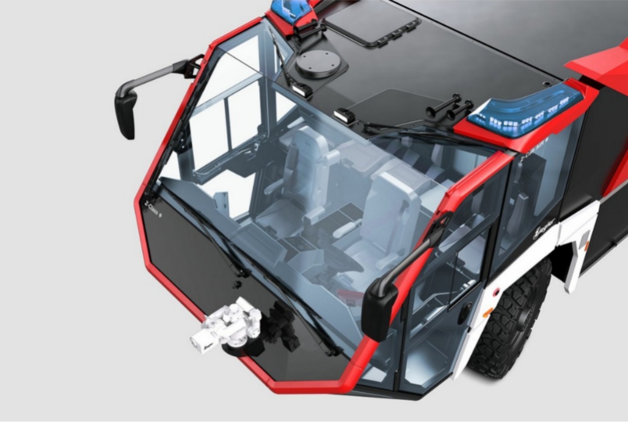
| 200 ZIEGLER Z-Cab Air: 1x K-950-000001 Ziegler Z-Cab Air Two-Door safety cabin Mounted for less torsion and less vibration inside the cabin. The cabin is made out of aluminum combined with GRP parts for high durability, high rigidity, and high-class corrosion resistance.  |
|||
| The Z-Cab Air has been designed, developed, and built under the consideration of safety and ergonomics. The Cabin is highly isolated against loud noises and ambient temperature. |
|||
| The tinted roof flat is integrated into the roof and is fully walkable. This flap is also the access to the manual emergency control of the roof turret or Z-Attack. Due to safety reasons, the flap is equipped with a control sensor which indicates an open flat. The large-scale front window so as the roof-, side-, door- and ground windows is made out of tinted laminated safety glass/tempered safety glass and guarantees for superior surround view for the crew. |
|||
| The ground surface of the cabin is made out of slip-resistant materials and has a smooth transition to the walls without any gap (up to 100 mm). | |||
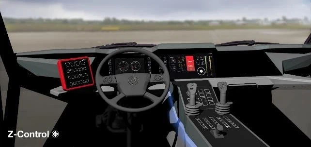
| The lighting concept of the cabin considers the specific requirements of the various operation and training scenarios. All gauges, switches, and control devices are glare-free and functional and integrated into the high-class control system Z-Control 2.0. |
|||
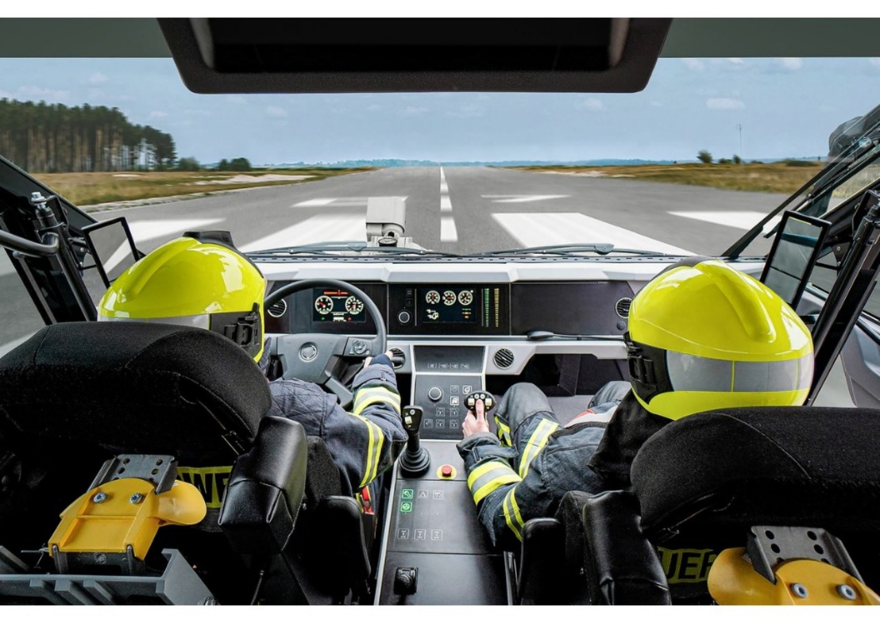
| The driver and the co-driver are both able to control the extinguishing system in the middle of the cabin. Every location of control devices, switches, and gauges is made under the consideration of ergonomics. Height inside the cabin: 1800 mm Horizontal driver field of view: approx. 210° Vertical driver field of view: approx. 75° 1x K-950-000005 Driver’s seat basic Air-suspended type, adjustable in the horizontal direction, with integrated 3-point safety belt in red color, seat covered with high resistant textile. |
|||
| 1x K-950-000043 co-driver seat with SCBA bracket (single bottle type) Unsuspended type, adjustable in the horizontal direction, with integrated 3-point safety belt in red color and SCBA bracket, seat covered with high resistant textile. 1x K-950-000077 Crew seat with SCBA bracket (single bottle type) Unsuspended type, with integrated 3-point safety belt in red color, seat covered with highly resistant textile. 1x K-950-000087 Crew seat with SCBA bracket (single bottle type) Unsuspended type, with integrated 3-point safety belt in red color, seat covered with highly resistant textile. |
|||
| 1x K-950-000150 Manually opening cabin doors The cabin is equipped with manually opening, and turning doors. The cabin guaranties perfect conditions for entering and leaving od the vehicle due to an entrance wide of 1000 mm. 1x K-950-000147 Solid mechanical stair treads fixed, oscillating suspended steps. Additional yellow handles on the left and right side of each entrance. |
|||
| 1x K-950-000153 Mechanical sliding windows 1x K-950-000168 Sunblind (roll-off type) for driver and co-driver1x K-950-000342 24V socket inside cabin |
|||
| 1x K-950-000343 Power outlet USB in cabin 1x K-950-000165 Windscreen wipers with window cleaner system and screen wash tank |
|||
| 1x K-950-000180 Electrical heated and adjustable main, wide and angle mirrors 1x K-950-000188 Electrical heated and adjustable curb mirror, right-hand side |
|||
| 1x K-950-000240 AC-unit with manual temperature regulation 1x K-950-000252 LED gooseneck reading light on dashboard for co-driver 1x K-960-000005 Alarm Start Unit |
|||
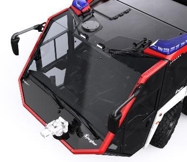
| 230 Signaling unit: 1x K-960-000019 Main flashlights blue Two flashlights integrated into the cabin, 1x left and 1x right side on top of the cabin |
|||
 |
|||
| 1x K-960-000030 Main rear flashlights blue Two corner flashlights integrated into the rear corner of the superstructure, 1x left and 1x right-hand side |
|||
| 1x K-960-000041 Signaling Unit Signaling unit with 1 loudspeaker |
|||
| 250 Radio and intercom unit (optional): 1x K-950-000268 Radio preparation 24V/12V 18A galvanic separated |
|||
| 260 Driver’s cab – control units: | |||
| 1x Discharge protection with audible warning for low voltage vehicle batteries from 24 V. When below 23 V in addition all charging devices are turned off. | |||
| 1x K-950-000200 Acoustic reverse gear warning unit, can be deactivated, with automatic adjustment with loudness on the ambiance noise | |||
| 1x K-950-000196 Reverse video system with a color camera mounted at the middle-top of the rear superstructure. The system is automatically activated by switching to the reverse gear. The video is displayed on an 8″ screen inside the cabin. | |||
| 300 Superstructure: The vehicle consists of modular components mounted distortion-free on the chassis independent from each other: |
|||
| – Driver’s cab – Pump locker – Equipment locker/water- / foam tank – Engine locker |
|||
| The individual components are modular mounted and can be separately lifted off after releasing the corresponding connections. | |||
| Both the pump locker and the engine locker are provided with large roller shutters and/or flaps. Additional maintenance flaps in the roof area. Suitable treads for maintenance works are mounted. Between the front and rear axles laterally left-hand side and right-hand side of the equipment boxes are located where the quick-intervention units respectively the equipment are provided. |
|||
| The front equipment locker is designed for storing the dry chemical powder unit and the equipment. | |||
| Thanks to large size lateral flaps optimum access to the fuel tank. All modules of the superstructure consist of the solid ZIEGLER aluminum system with screwed light structural profiles (ALPAS). |
|||
| Thanks to this profile system variable inside installation. Thus, subsequent alterations are possible with minimum effort. | |||
| The equipment boxes between the axles are shut by splash-water and dust-proof aluminum roller shutters, on the left-hand side and right-hand side. | |||
| Roller shutters with the patented ZIEGLER AZ-LOCK (grip/rod shutter), lockable. | |||
| Equipment locker LED lighting by electro-magnetic switches. | |||
| The equipment lockers and parts of the partitions and shelves are made of aluminum double-padded plates. | |||
| The fire-fighting equipment is safely and practically stored in the equipment boxes, in the equipment locker, and the driver’s cab and can easily be removed. | |||
| Access to the roof is made via a self-stopping hinged ascending ladder rear side respect. Via the roof hatch from the cabin. 1x K-960-000113 Manual fall protection guardrail |
| 310 Lighting superstructure: | |||
| 1x K-960-000074 Ambiance lighting consisting of LED searchlights, left-hand side, and right-hand side, switchable from driver’s cab and pump bay 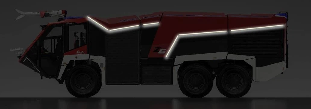 |
|||
| 1x K-960-000050 Traffic lighting at the front 2x Halogen low-beam light |
|||
| 2x Halogen high beam light 2x Parking light 2x Direction indicators Contour lighting |
|||
| 1x K-960-000057 Two front fog lights | |||
| 1x K-960-000068 Traffic lighting at the rear 4x Tail light 4x Brake light 4x Direction indicator 1x Rear fog light 1x Reverse light Lighting for the license plate 1x K-960-000063 Additional front ambiance lighting on top of the cabin |
|||
| 1x K-960-000071 Additional ambiance lighting at the rear of the superstructure | |||
| 1x K-960-000076 Roof lighting (LED) for roof turret version | |||
| 400 Centrifugal fire pump: 1x K-970-000005 Single-stage centrifugal fire pump FPN 10-8000-1M Nominal output: 8.000 l min-1 @ 10 bar 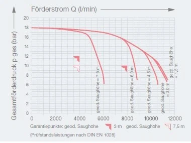
|
|||
| Materials: 1. Castings (impeller, pump cover, pump housing) are made from sea-water resistant light metal alloy. 2. The pump shaft and split water rings are made from corrosion-resistant stainless steel. 3. Drain cocks are made from brass. |
|||
| Priming system: Automatic priming system. Advantages: The fire extinguisher centrifugal pump with its attachments is robust extremely reliable and designed insensitive to dirty water. For venting no foreign media are required. Drive: The fire extinguisher centrifugal pump is driven by the vehicle engine via a cardan shaft train from the p.t.o of the transmission. |
|||
| Installation: The fire-extinguishing centrifugal pump is installed in the rear of the vehicle in the pump chamber. Control: All switching operations for pump operation are made at the pump control station near the centrifugal fire pump. The fire extinguisher pump is switched on by the standard PTO switch in the pump bay via the Z-Control. |
|||
| Equipment normal pressure pump: 1x suction line, open diameter 250 mm, remote-lockable by butterfly valve 1x K-970-000118 external suction inlet DN150 mm, with tight STORZ coupling and blank cap, lockable, left-hand side 1x K-970-000050 2x delivery outlet DN65 mm, lockable, with tight Storz B coupling and blank cap, left-hand side 1x K-970-000070 2x delivery outlet DN65 mm, lockable, with tight Storz B coupling and blank cap, right-hand side 1x drain cock at the fire pump 1x Pressure outlet, open diameter 125 mm, to the roof water turret, remote-controlled lockable 1x Pressure outlet, open diameter 75 mm, to the front water turret, remote-controlled lockable 1x Pressure outlet, open diameter 50 mm, for self-protection system, can be shut off remotely 1x K-970-000087 Pressure outlet, to the rapid attack device normal pressure, lockable, left-hand side 1x K-970-000092 Pressure outlet, to the rapid attack device normal pressure, lockable, right-hand side 1x Feed water line, open diameter 32 mm, remote-controlled |
|||
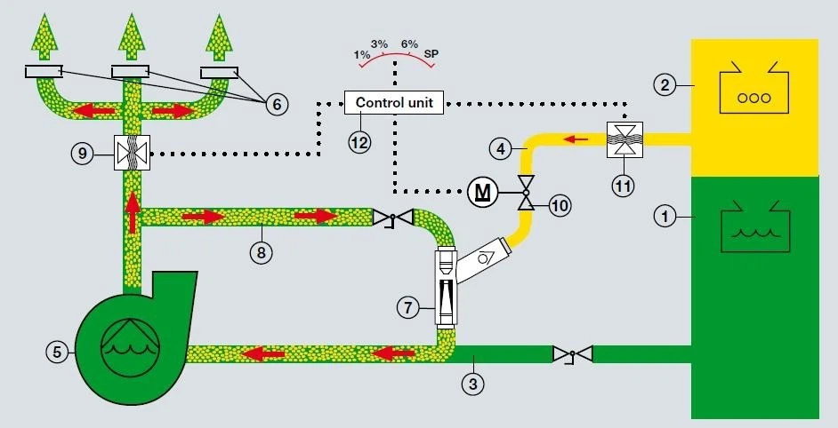
| 1x K-970-000032 Pump pressure control unit TOURMAT D 410 Foam admixing system: 1x K-970-000026 ZIEGLER EAD consisting of: Electronic automatic dosage unit designed for a performance of 200 l/min up to 8.000 l/min flow rate. Proportioning of the foam agent is made in a constant ratio with the water flow. The proportioning rate can be adjusted infinitely from 1% up to 6 %. Adjustment of the proportioning rate is made remote-controlled from the driver’s cab and at the pump, operations stand. Basic adjustment 3 %. |
|||
| ZIEGLER ZPV Pump proportioner driven via the feed water line of the pump by a partial stream of the pressurized water.
|
|||
| 420 Piping: All piping is corrosion-resistant, stainless steel pipe or equivalent respectively rubber hoses and non-deformable plastic hoses. |
|||
| The piping system is designed so that after each use the piping can be flushed. The shut-off valves from the flushing lines and the foam lines are mutually secured so that no water can get into the foam concentrate tank at flushing. All piping can be centrally drained from the pump. | |||
| All valves for delivery of extinguishing agent are easy to maintain and easy to handle. They are provided with a mechanical emergency operation. | |||
| 430 Quick intervention unit: 2x Quick intervention hose reel Installation: one hose reel left-hand side in the lower equipment locker and one hose reel right-hand side in the lower equipment locker (in total two hose reels) |
|||
| Type: Connected with the centrifugal fire pump. |
|||
| Each reel is provided with a 30 m delivery hose and DN 32. | |||
| 440 Ziegler Roof Turret ZT-6000 1x K-940-000001 Combination pipe type with deflector and change-over unit 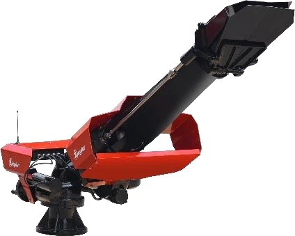 |
|||
| Output: 6.000 l/min / 3.000 l/min at 10 bar (water-foam) | |||
| The deflector is remote-controlled and infinitely variable. | |||
| Control: the turret is remote-controlled and moved by a joystick. By the joy-stick horizontal and vertical movements can be made simultaneously. By a push button being integrated into the joystick, the turret locking flap between the pump and turret is actuated. |
|||
| Thanks to proportional control fine control of the turret is possible, i.e. variable turret speed corresponding with the steering of the joy-stick. |
| Change-over unit: The flow rate of the turret is remote-controlled and adjustable from 100 % to 50 %. | ||
| Limit switch: | The horizontal and vertical movements are limited by mechanical limit stops and electrical limit switches. Manual emergency operation by hand wheels is possible. | |
| Throw shield (deflector): At the multiple gallonage nozzle (respectively at the foam pipe) a double deflector is put on. Adjustment is remote-controlled. Emergency manual operation by lever. |
||
| Further equipment: 2 LED-searchlights in throw direction with automatic activation of the searchlights at the turret attack. |
||
| Bearing: | The rotating parts are vertically and horizontally arranged on ball bearings. This design guarantees a permanent safe and constant movement. |
|
| Material: | The water-bearing parts of the turret are made from light metal G-AlMg3, anodized, and additionally, they are electrostatically lined (KTL special treatment). The drive spindles are made from stainless steel, and the worm wheels are made from bronze. |
|
| Technical data: Throws: 6.000 l/min: water approx. 90 m (full jet, far point) foam approx. 85 m (full jet, far point) 3.000 l/min: water approx. 60 m (full jet, far point) foam approx. 55 m (full jet, far point) Horizontal movement: Approx. 270 degrees Vertical movement: Approx. -15 degrees approx. +70 degrees (dependent on superstructure) Geared engines: 24 V D.C. kind of protection IP 65 |
||
| 440 ZIEGLER bumper turret 1x K-940-000040 Ziegler bumper turret 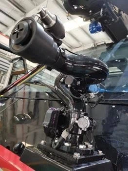 |
||
| Output: Water/foam approx. 1800 l/min at 8 bar |
||
| Control: The turret is remote-controlled and moved by a joystick. By the joystick horizontal and vertical movements can be controlled simultaneously. |
||
| Technical data: Horizontal movement: approx. 180 degrees Vertical movement: approx. –25 degrees / approx. +70 degrees Geared engines: 24 V D.C., IP 65 with manual emergency operation |
||
| Throws: 1800 l/min and 8 bar: water approx. 60 m 450 Ziegler self-protection system |
||
| 1x K-940-000051 The body/ground protection unit consists of 2 front fan pattern spray nozzles and 4 ground nozzles (in total 6 nozzles) laterally of the vehicle with a total output of approx. 350 l/min at 10 bar. The body/ground protection unit is used for protecting the rear and front wheels against ground fires. | ||
| Front nozzles: At the front side, 2 front fan pattern spray nozzles are provided. The foam fan pattern spray nozzles are mounted and have a throw of approx. 5 m as well as a width of throw of 6 m for each nozzle. Output of each nozzle approx. 125 l/min at 10 bar |
||
| Ground nozzles: Laterally at the vehicle in the area of the electric and pneumatic lines 4 ground nozzles are mounted and connected with the front fan pattern spray nozzles through a joint extinguishing agent feed line. Output of each nozzle approx. 25 l/min at 10 bar. |
||
| Opening respectively shutting off the body/ground protection nozzles is made from the control panel in the driver’s cab. All nozzles are activated simultaneously. | ||
| 490 Control and adjustment: The control elements of the extinguishing unit are located in the driver’s cab on a console, operated by the driver and co-driver. |
||
| In the driver’s cab, a control panel is installed between the driver and the co-driver. Thus, optimum operation of the joy-sticks optionally by the driver or the co-driver. | ||
 |
||
| Furthermore, one color display as an operating panel is mounted at the pump operator’s stand left-hand side. | ||
| For the operation of the corresponding water and foam bearing armatures, the compressed air being already available at the engine is used as an energy carrier. | ||
| Control is made electro-pneumatically by CAN-BUS technology. | ||
| As operating elements for the primary functions of the firefighting superstructure toggle push buttons are used. With symbols within the button and a description field below the button. | ||
| The operating conditions are indicated by control lights. | ||
| 1. Search lighting function OFF 2. Flashing function will be made 3. High-power light function ON (ready signal) The control elements for secondary functions and indications are comprised of functional groups in the TFT color displays. |
||
| The control elements of the displays are designed as pushbuttons respect. Rotary potentiometers each being surrounded by an illuminated ring. | ||
| All switch elements are provided with a switch control/function control. Thanks to the use of a continuous CAN-BUS crosslinking of chassis and superstructure electronics both data of the chassis and the firefighting superstructure are provided in the TFT displays and also can be recalled there. |
||
| Control panel in the driver’s cab: | ||
| This control desk comprises all indicators, switches, and levers necessary for remote control of the fire-fighting and body/ground protection unit. |
||
| Operation of the extinguishing unit is done automatically after pressing the corresponding quick-action key so that operating errors are eliminated and the operator can concentrate entirely on the fire-fighting task. | ||
| After pressing the quick-action key (water/foam), e.g. for foam operation the following functions will be triggered automatically: | |||||
| 1. The water tank suction line will be opened | |||||
| 2. The pump unit with the centrifugal fire pump will be switched on | |||||
| 3. The pump rpm (pressure) will be adjusted automatically to the preselected value by the Tourmat D automatic system | |||||
| 4. The suction line of the foam tank and the feed water line for the proportioner will be opened | |||||
| The control desk is provided with the following switches and indicators. The number and arrangement of the keys and indicators can vary according to the special equipment selected. The following list is an example. |
|||||
| Switches/keys: | |||||
| Master switch (extinguishing unit) | ON | OFF | |||
| Water operation | ON | OFF | |||
| Foam operation | ON | OFF | |||
| Pump pressure preselecting TOURMAT D | 0 | up to | 16 bar | ||
| TOURMAT D Automatic system | ON | OFF | |||
| Proportioning rates | 1% | up to | 6% | ||
| Body/ground protection system | ON | OFF | |||
| Water/foam hose reel | ON | OFF | |||
| Roof-turret water/foam: | |||||
| Joy-stick | UP LEFT |
DOWN RIGHT |
|||
| Turret valve (water-foam) | OPEN | SHUT | |||
| Jet pattern | full jet | spray jet | |||
| Roof turret | ATTACK | BRACKET | |||
| Flow rate | 100 % | / | 50 % | ||
| Bumper turret water/foam: | |||||
| Joy-stick | UP LEFT |
DOWN RIGHT |
|||
| Jet pattern | full jet | spray jet | |||
| Turret valve (water-foam) | OPEN | SHUT | |||
| Bumper turret | ATTACK | BRACKET | |||
| The following indications are realized clearly in a colored TFT display according to the chosen quick-intervention key: | |||||
| Extinguishing unit: Contents indication water Contents indication foam Output pressure low-pressure pump Compressed air gauge Pump temperature Position indication roof turret Position indication roof turret |
|||||
| Pump drive: Rpm counter Working hour recorder pump drive |
||||
| Further controls and indicators in the driver’s cab: | ||||
| Driver’s door | OPEN | SHUT | ||
| Co-drivers door | OPEN | SHUT | ||
| Emergency operation tread | ON | OFF | ||
| Control of the air conditioning unit | ON | OFF | ||
| Flashlights | ON | OFF | ||
| Acoustic signaling unit | ON | OFF | ||
| Roof lighting | ON | OFF | ||
| Ambiance lighting | ON | OFF | ||
| Cab lighting | ON | OFF | ||
| Compartment light master switch | ON | OFF | ||
| Batterie main switch | ON | OFF | ||
| Adjustment of main / ramp mirror | ||||
| Equipment locker control | ||||
| Turret bracket control | ||||
| Voltmeter | ||||
| COLOURED TFT DISPLAY AS CONTROL PANEL AT THE PUMP OPERATOR’S STAND: | ||||
| 1x K-970-000201 Pump control station left | ||||
| Switches/keys: | ||||
| Engine | START | STOP | ||
| Engine shut down switch. | . | |||
| Pump drive | ON | OFF | ||
| Tank suction water | ON | OFF | ||
| External suction operation water | ON | OFF | ||
| Tank suction operation foam | ON | OFF | ||
| External suction operation foam | ON | OFF | ||
| Proportioning rates | 1 % | up to | 6 % | |
| Foam tank filling | ON | OFF | ||
| Flushing pump unit | ON | OFF | ||
| Tank filling/circulation operation water | ON | OFF | ||
| Level adjustment water tank | ON | OFF | ||
| Pump pressure preselection Tourmat D | 0 bar | up to | 16 bar | |
| TOURMAT D Automatic system | ON | OFF | ||
| Draining pump unit | ON | OFF | ||
| Roof lighting | ON | OFF | ||
| Ambience lighting | ON | OFF | ||
| The following indications are shown clearly in colored displays according to the selected quick-action key: | ||||
| Extinguishing unit: Contents indicator water Contents indicator foam Mano-vacuum meter low-pressure pump Outlet pressure low-pressure pump Compressed air gauge |
||||
| Pump drive: | ||||
| Rpm counter Working hour recorder pump drive |
||||
| PNEUMATIC EMERGENCY OPERATION OF THE EXTINGUISHING UNIT: | ||||||
| The following functions can be triggered directly pneumatically via pilot valves in case of an electric breakdown from the control panel in the driver’s cab: Emergency operation of extinguishing unit: | ||||||
| 1x K-950-000325 | Main air | OPEN | SHUT | |||
| 1x K-950-000326 | Water tank | OPEN | SHUT | |||
| 1x K-950-000327 | Foam tank (incl. feed water) | OPEN | SHUT | |||
| 1x K-950-000328 | Roof turret extinguishing agent | OPEN | SHUT | |||
| 1x K-950-000329 | Bumper turret extinguishing agent | OPEN | SHUT | |||
| 1x K-950-000330 | Body-ground protection system | OPEN | SHUT | |||
| Emergency operation pump engine: | ||||||
| 1x K-950-000332 | Rpm – pump | + | – | |||
| 1x K-950-000331 | Pump | START | STOP | |||
| All shut-off units can be manually operated in emergencies after opening of the main air valve. | ||||||
| Control elements at the low-pressure hose: | ||||||
| Recoiling reel | ON | OFF | ||||
| Water/foam | OPEN | SHUT | ||||
| Reel brake | ON | OFF | ||||
| 600 Brackets for equipment: Necessary brackets and fixings for equipment are installed. |
||||||











Reviews
There are no reviews yet.